This free, five-part course will guide you through the design of a kinematic mount for your own custom, real world application: from theory, to design and analysis, to CAD modeling, to production.
The course includes parametric CAD models of several kinematic mount designs, which you can use to explore the concepts discussed and freely adapt for your own work.
This course covers:
- The principle of kinematic constraint and its application to kinematic mounts and couplings
- How to optimize the layout of a kinematic mount for real world, often constrained applications
- Designing the kinematic interface, while considering contact stress, stability, and repeatability
- Selecting materials for kinematic mounts
- Adjustments and locking mechanisms
In addition to the guided course and kinematic mount CAD models, you’ll receive an Introduction to Precision Machine Design and access to additional resources and articles as they are released.
A Key Piece of the Precision Design Toolbox
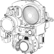
Precision machine design and optomechanical engineering are the domain of deflection – designing a thing so it can hold a position, move to a position, or follow a position with a level of accuracy that is many orders of magnitude smaller than the size of the thing itself.
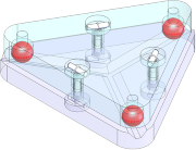
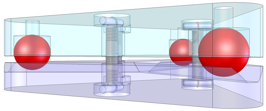
Kinematic mounts and couplings are a critical tool for achieving these goals. They locate and orient one rigid body relative to another using up to six point contacts. Each point contact removes one of the six degrees of freedom (3 rotations and 3 translations), precisely constraining the bodies in that DOF while leaving them free to move relative to one another in the others. A well-designed kinematic mount is stable and repeatable, resisting changes in position and orientation due to environmental or operating loads, and returning to the same position and orientation if separated (intentionally or unintentionally).
We’ll look at the classic forms of kinematic mounts – the plane, v-groove, and trihedral socket of the Kelvin clamp and the three radiating v-grooves of the Maxwell clamp – as well as custom forms that satisfy the space claim, tool access, and other constraints of your design.
We’ll explain fundamental principles and calculations such as Hertzian contact stress, provide guidelines and best practices, and cover the practicalities of modeling and machining in SolidWorks, Inventor, and other CAD systems.
A practical kinematic mount design is not complete without means to preload the rigid bodies against each other and – often – to adjust the allowed degrees of freedom, then lock them in place. The chosen method must not over-constrain the system, introduce instability, or deform the bodies in a way that defeats the purpose of using a kinematic mount in the first place. We’ll review each of these topics in detail.
Kinematic Mount Design Articles
The outline of the series and links to the completed articles are below. If you’d like to be notified as new articles and resources are released, sign up below.
You’ll also receive the Precision 101 Guide and related CAD models. Experiment with the models and adapt them for your own use. It’s an example of the power of the active learning approach used in all Practical Precision tutorials, ebooks, and courses & the immediate value of being able to use the models in your own work.
- Introduction to kinematic mount design
- A visual guide to kinematic mount design
- The principle of kinematic constraint
- Classic forms of a kinematic mount design: The Kelvin clamp and the Maxwell clamp
- Kinematic mount designs for real world applications
- Modeling and design of a kinematic mount in CAD (using SolidWorks)
- Laying out a kinematic mount using the Maxwell criterion – How to optimize the layout of a kinematic mount for stability and repeatability using the Maxwell criterion
- Selecting Materials for Kinematic Components – Kinematic components are the set of balls, vees, and other shapes that come into point contact with each other to locate the structural members of a kinematic mount relative to one another. In this article, we discuss the desirable material properties of kinematic components and the criteria used to evaluate materials for your kinematic mount design. We also provide a quick reference sheet for comparing the relevant properties of common kinematic component materials to help you select the right material for your design.
- Machining and modeling trihedral sockets for a kinematic mount
- Machining and modeling v-grooves for a kinematic mount
- Laying out a kinematic mount design
- Hertzian contact stress in kinematic mounts – One disadvantage of kinematic mounting is the high Hertzian contact stresses that develop at their point contacts. This is often seen as limiting kinematic mounts to light duty applications. Even calculating contact stress is complex, which can deter engineers from considering them or fully exploring the design space. This article and the included worksheet will help engineers to easily calculate Hertzian contact stress, allowing them to explore more design alternatives for more applications of kinematic mounts.
- Preload mechanisms for kinematic mounts
- Adjustment mechanisms for kinematic mounts
- Locking mechanisms for kinematic mounts
- Material selection and finish specification for kinematic mounts
- Tolerance and error analysis for kinematic mounts