
Kinematic mounts are one of the most powerful tools in precision machine design and optomechanical engineering. In this video, we look at modeling and designing a kinematic mount in CAD, using SolidWorks. We briefly review specific aspects of kinematic mount design – such as kinematic constraint, preload mechanisms, and contact stress – as well as the construction of this particular CAD model and how to adapt it to your needs.
To download this CAD model of a Maxwell-style kinematic mount, explore the concepts we discuss, and freely adapt it for your own use, click the link below:
The model is also available in neutral CAD formats, such as Parasolid and STEP. If you would like a native version for the CAD system you use, drop me a line on the contact page.
For clarity, I’ve left out some details that would be present in an real application, so that we can focus only on the details that make it a kinematic mount.
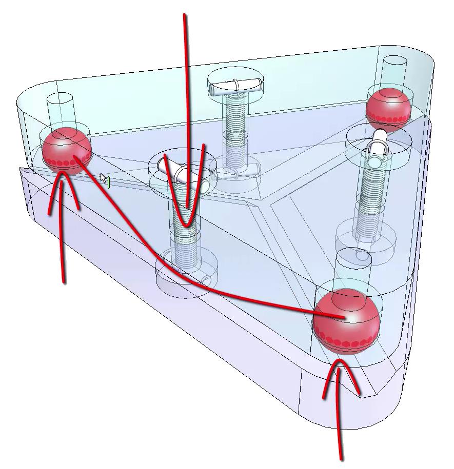
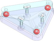
Kinematic constraint of a Maxwell-style kinematic mount
For detailed information on the theory of kinematic mounting – including information about unconventional kinematic interfaces, such as three balls on a spherical surface – checkout The Principle of Kinematic Constraint.
In short, the principle states that any two rigid bodies have six relative degrees of freedom (DOF) between them – three rotations and three translations – and for each point of contact between the bodies, one degree of freedom is eliminated:
- Six points of contact completely and precisely locates and orients one relative to the other
- Fewer than six allows precision motion in the remaining degrees of freedom
- More than six over-constrains the assembly, introducing distortion, instability, and uncertainty
A Maxwell-style kinematic mount uses three balls in three v-grooves radiating from a common center to establish six points of contact, exactly constraining the two halves to each other.
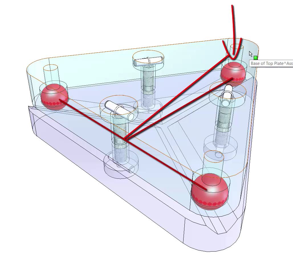
In some applications – such as when interchangeability between mass produced components is a key requirement – the mount will be used as shown: with each of the balls fixed. The subassemblies being joined will be pre-aligned using an external fixture that replicates the mounting features. Thus, any subassembly can be replaced with any other (in production or in the field) with very high accuracy.
The v-grooves radiating from a common center even allows a single base to be used with multiple mating subassemblies of different sizes, with the balls spaced for optimal support. This is one reason that the Maxwell-style kinematic mount may be chose over the “classical” Kelvin clamp form.
In applications that require adjustment and alignment in place, one or more of the balls will be replaced with a ball end adjustment screw. Adjustments about two axes (tip-tilt) are possible, although the adjustment isn’t quite as intuitive as in a perpendicular arrangement. If all three of the balls are replaced by adjustment screws, it’s even possible to adjust the spacing between the subassemblies without changing the orientation.
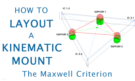
Modifying the layout of the kinematic mount
This kinematic mount model uses top-down design, so that we can make changes in one place at the assembly level, and those changes will propagate down to the components. That place is the Layout component, which is the first component in the assembly tree. The Layout component contains two sketches that we will use to make changes to the rest of the assembly:
- The LayoutContacts sketch controls the basic layout of the mount, including the spacing and angle between the supports
- The ContactCrossSection sketch controls the diameter of the calls and their contact angle with the v-grooves
In this section, we’ll look at the modifying the layout using the LayoutContacts sketch.
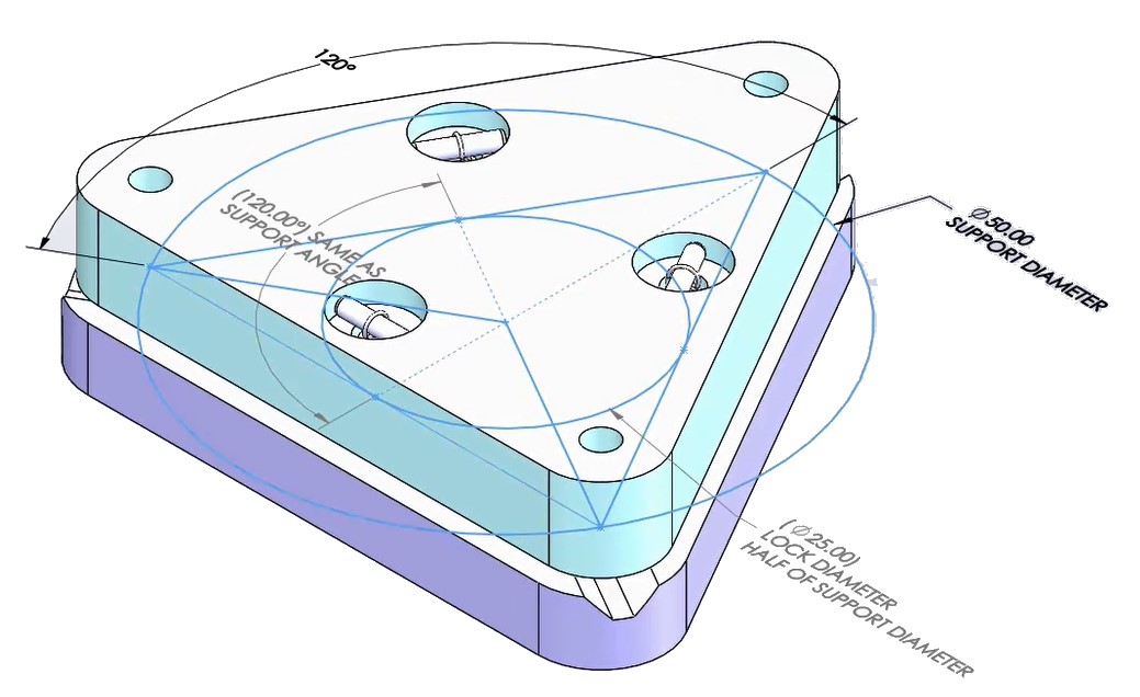
The equilateral triangle layout is the most common and the default for the model. It maximizes usable area; is very stable; and can be less sensitive to transient thermal effects due to its symmetry.
But there can be practical reasons for deviating from this. The most common reason is that an equilateral layout simply won’t fit in the space available.
Changing this layout is as simple as changing the diameter and angle dimensions in the Layout Contacts sketch. The rest of the features will update accordingly.
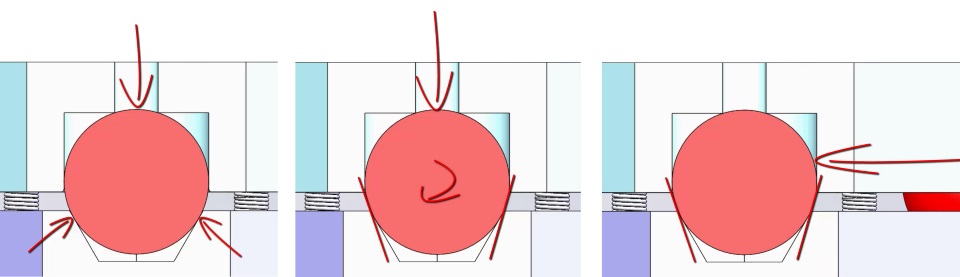
Modifying the ball diameter and contact angle
In this design, the balls are press-fit into the top plate so that they can’t move relative to it. But the combined ball/top plate is free to rotate about the center of the ball, on the two points of contact with the v-groove in the bottom plate. And the v-groove actually has a flat between the two angles sides.
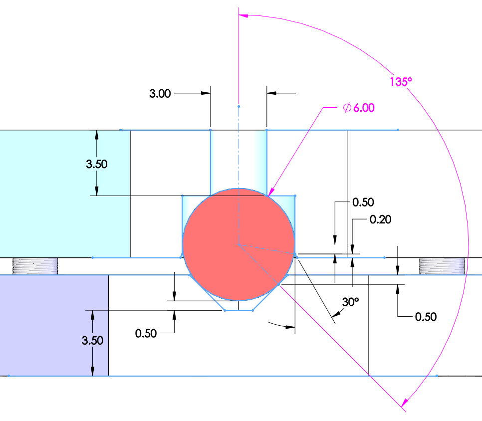
The ContactCrossSection sketch controls the diameter of the ball and the contact angle.
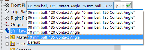
The ball diameter and the contact angle could be infinitely variable, just like the spacing and the angle between the supports are in the LayoutContacts sketch. But as a practical matter, precision balls are only readily available in discrete diameters, as are tools for machining smooth surfaces at particular angles.
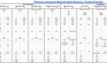
So in this model, we have a fixed number of ball diameter and contact angle combinations, with diameters ranging from 6 to 10 mm and angles of 120 and 135 degrees. These are saved as configurations of the Layout part. You can select one or create additional ones for the cases you commonly use.
The model is set up to maintain critical clearances – regardless of the diameter of the ball or the contact angle – so that it accommodate manufacturing tolerances:
- On the top plate, the center of the ball sits 0.5 mm below the flat surface, so that there is always a press-fit between the two.
- On the bottom plate, the contact points between the ball and the v-groove are 0.5 mm below the flat surface.
- On the bottom plate, there is 0.5 mm clearance between the bottom of the ball and the bottom of the v-groove.
Defining the kinematic contacts: Ball diameter, contact angle, and material
The design of the kinematic contacts – the radii of the surfaces, the contact angle between them, and the material of each contact component – is critical to the performance of your kinematic mount, including repeatability, stability, and operating life. You must consider:
- Hertzian contact stress, deflection, and stiffness
- Friction and freedom of movement
- Stability
These topics are briefly introduced below and will be expanded on in their own articles.
Hertzian contact stress, deflection, and stiffness
One significant disadvantage of a kinematic mounts is that it supports the combined internal and external load on only six points, which can produce high Hertzian contact stresses, which can cause immediate or long-term damage to the interface.
Contact stress is a function of the load, the geometry, and the material properties of the components.
What’s an acceptable level of contact stress depends on the yield stress of the components. The modulus of elasticity of the components also factors into the the calculation of the contact stress. As does the diameter of the ball. So material choice and ball diameter are the primary variables at your disposal. Interesting things can also be done with the geometry, such as using canoe balls.
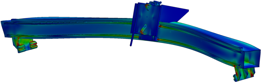
In the process of calculating the Hertzian contact stress, you will also calculate the deformation of each component and the relative displacement or deflection between them. With this, you can in turn calculate the stiffness of the kinematic contact. Low deflection and high stiffness are particularly important in systems that require high measurement or position accuracy, especially in the presence of variable loads.
Friction and freedom of movement
For smooth, linear operation of any adjustments and long-life of the joint, the ball needs to slide freely on the surface. That is principally a function of friction and all that that entails, including the normal force, the friction coefficient between the materials, and the surface friction. Lubrication can help, but common lubricants can attract gunk that hurts more in the long term than it helps.
The contact angle also plays a role. It’s easy to visualize in the extreme case of a very steep v-groove, with the ball becoming wedged and immobilized under the load.
Stability
But steeper angles also have benefits:
- More resistant to lateral loads
- If a ball is unseated due to shock, vibration, or other external load, it will more readily fall back into place
- Overall repeatability is higher
With these related and sometimes contradictory design parameters, careful design and analysis is required.
Preload mechanisms for kinematic mounts
Depending on the orientation of your mount, the magnitude of the load it will carry, and any external loads such as shock and vibration, you’ll need a mechanism to positively load the kinematic components against each other, so that they don’t separate.
This is a critical aspect of the design, as there can be a delicate balance between:
- Sufficient locking force to hold the mount together against the combined loads
- Excessive force that significantly deforms the components, defeating the purpose of using a kinematic mount in the first place.
Learn more in the Kinematic Mount Design series
This articles is part of the Kinematic Mount Design series, where we explore the aspects of kinematic mount design in detail, including first principles like kinematic mounting and practical considerations like machining trihedral sockets.
Visit the Kinematic Mount Design page to learn more and to me notified of future articles.

I revised the section on the design of the kinematic contacts for clarity. I’m currently writing an article on Hertzian contact stress in kinematic mounts to address one of the most common questions I receive about kinematic mount design.