Split clamps are a simple, robust method for securing cylindrical components that need to be adjusted axially (e.g., focusing a lens) or rotationally (e.g., a prism holder) that satisfy one of the principles of good locking mechanism design: A locking mechanism’s action should not influence the sensitive adjustment that it is intended to secure. But while the resulting mechanism is simple and robust, a successful split clamp design for a custom optomechanical application requires careful thought and analysis.
A locking mechanism’s action should not influence the sensitive adjustment that it is intended to secure.
A split clamp satisfies this criteria for both the lens cell and the prism holder: Tightening the clamp does not move the lens cell axially or rotate the prism mount. The adjustment and the locking mechanism are said to be orthogonal to one another.
Contrast this with a threaded lens cell in a threaded mount that is locked by tightening a jam nut against the mount. The jam nut will take up the backlash between the threads, shifting the lens axially. It will also impart a slight rotation to the lens cell, advancing the threaded body and further shifting the focus.
A close fit between the mating parts minimizes other uncertainties (e.g., tilt) in the mechanism when the clamp is loose. But too tight can create stick-slip operation and a frustrating tendency to bounce around the ideal set point. Alternatively, the bore could be produced slightly under-sized and sprung open with a lever when making the adjustment.
Basic and Collet-Style Split Clamp Design
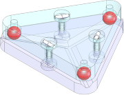
The figure below shows two forms of split clamp:
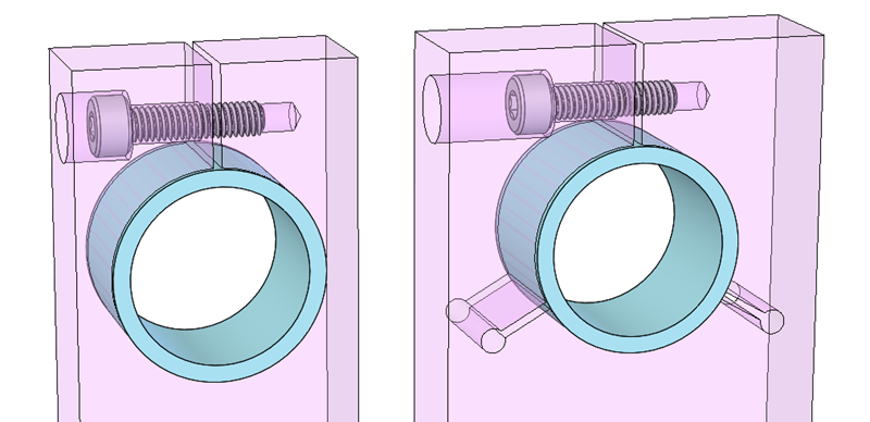
Figure: Basic (left) and collet-style (right) split clamp designs
- The left is the basic form that I was introduced to in my first job. The basic split clamp has the advantage of being compact, a practical consideration in applications with a tight or unusual space claim.
- The right is a collet-style, discussed in Dave Kittell’s little blue book, Precision Mechanics. The reliefs, spaced approximately 120 degrees apart, are intended to allow the clamp to act like a collet, closing in uniformly around the component.
Kittell introduces the collet-style split clamp while describing how to build a precision adjustment mechanism using simple techniques and readily available parts, including a 3/8-24 UNF screw as the actuator. The clearance in standard screw threads is enough that lateral forces can cause a skew which can measurably impact position. Kittell rates a simple threaded hole as really bad and the basic split clamp as only fair, being relatively tight in the horizontal plane but relatively loose in the vertical plane.
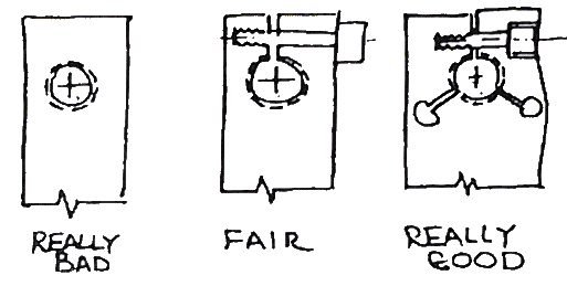
Figure: Source: Precision Mechanics, by Dave Kittell
Intuition can be a tricky thing as we move from the scale of human perception to the precision scale.
Intuitively, one can see that the advantage of the collet-style should be greater uniformity and improved stability, at the expense of space. But intuition can be a tricky thing as we move from the scale of human perception to the precision scale, and as the actual design of a thing deviates from the familiar and simplified models that we know and understand:
- A true collet chuck has a cylindrical inside diameter (ID) and tapered outside diameter (OD), which is forced into a matching tapered hole, so that the ID closes in uniformly around the tool or work piece being held.
- The actuation of the collet-style split clamp (as well as the basic split clamp) is clearly not symmetrical. A single screw squeezes one of the splits together. Reliefs at the end of the other two slots act as hinges, allowing all of the lobes to move at the same time, although not in the same way.
- In addition, an infinite number of geometries can satisfy any given application, with the performance depending on the nominal diameter, the nominal clearance, the location of the hinge points and the actuating screw, and the thickness of the hinge (the distance from the relief to the edge of the part.
Our intuition needs to be checked on the way to a final design.
The First Order Solution: A Feasible Concept that Fits
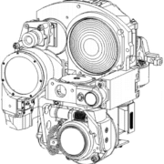
In practical applications, especially complex, highly integrated systems like gimbals and hand-held imaging devices, the first order problem is usually to develop a feasible concept that works in the space available. This is done based on engineering principles, wisdom/experience (received and your own), and intuition. It may involve trade off analyses, such as between the basic split clamp, the collet-style split clamp, or another locking mechanism altogether.
We develop our understanding of the interactions, loads, stresses, and deflections involved as we create free body diagrams (FBD) and perform hand calculations, using simple approximations such as cantilever beams for the legs of the basic clamp. A resource like Roark’s Formulas for Stress and Strain greatly expands our options and provides better approximations over what can be found in a standard machine design textbook.
A quick finite element analysis (FEA) study can further test your insights and assumptions. Completing the previous step first is critical, because an FEA requires YOU to define reasonable inputs and boundary conditions, without which the results may not be valid, no matter how pretty the pictures it produces. Both sets of results can then be used to check each other and to enhance your understanding of the more complex system.
Clamping a Lens Cell or Other Thin-Walled Cylinder
To develop our understanding of the split clamp design – especially the relative stability of the two design forms – let’s analyze a relatively large, thin walled cylinder, analogous to a lens cell or a prism holder that would translated or rotated, then locked in place.
I analyzed the split clamp designs shown above. The nominal outside diameter (OD) of the lens cell is 25 mm and the inside diameter (ID) is 21 mm. The thickness of the clamp (and therefore the length of engagement) is only 15 mm. This is a low length:width aspect ratio. Longer engagement and a larger aspect ratio are desirable because they reduce angular errors and the tendency to cock while translating. But this is based on an actual application in which the clamp thickness was limited by other constraints.
I analyzed two clearance cases for each design:
- Zero clearance between the cylinder and the bore
- .05 mm diametral clearance (0.2% of the nominal OD)
The clearance case is more computationally intensive (i.e., the FEA takes longer to run), because the contact condition and the stiffness of the geometry changes significantly once the clamping force is applied. The FEA solver must iterate through the solution so that it doesn’t miss this change and produce erroneous results. It may be tempting to only analyze the simpler case, but as we’ll see, the results different significantly. We don’t want to overly simplify the analysis model at this stage, commit to a design, and not realize until it’s too late that we missed an important detail.
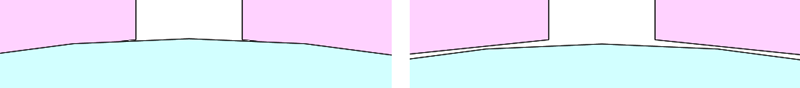
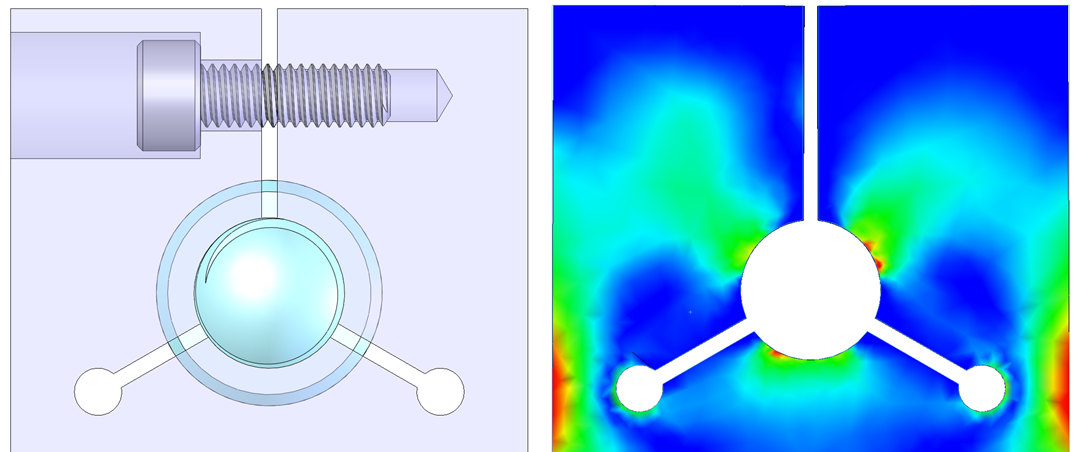
Figure: Two fit-cases were analysed: Zero-clearance (left) and 0.2% clearance (right)
Design Criteria
- Clamping uniformity and stiffness – The performance of an ideal split clamp would be similar to a shrink fit: Both the clamp and the lens cell would remain perfectly round and there would be uniform pressure all around. To evaluate this, we’ll examine the contact pressure between parts and the deformed shape of the cell.
- Yield stress – Split clamps can develop significant stress, especially in cases with relatively large clearance, and minor variations in geometry can have a significant impact on this. To securely hold the element under operating loads, it is important to verify that the clamp does do not develop a permanent set.
We’ll look at the clamping for each case first, followed by the stress for both cases.
A Note on Symmetry: I took advantage of the front-to-back symmetry of both the geometry and the loading in the analysis, sectioning the model about the plane of symmetry, applying the appropriate boundary conditions to the section faces, and analyzing only the front half of the model. I provide more details about this at the end of this article. For now, keep in mind that the results that you see in isometric views would be mirrored about the plane of symmetry for the part of the model not shown.
Case 1: Zero Clearance Between Lens Cell and Clamp
In the zero clearance case, contact pressure in appears relatively uniform in both the basic and the collet-style designs. In the front view, we see peaks that are significantly higher than the average. In the isometric view, it is clear that these correspond to sharp edges of the clamp. This is likely a real effect, overstated by the coarseness of the mesh.
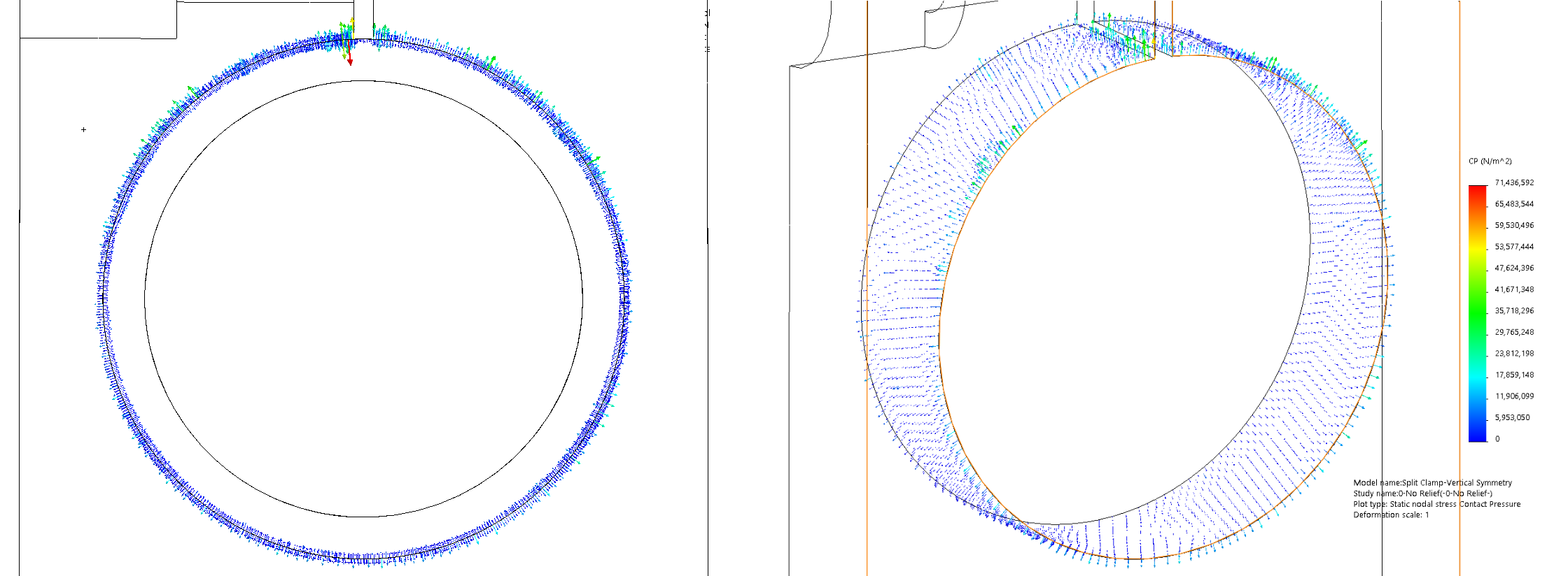
Figure: Contact pressure in a split clamp holding a lens cell with zero clearance
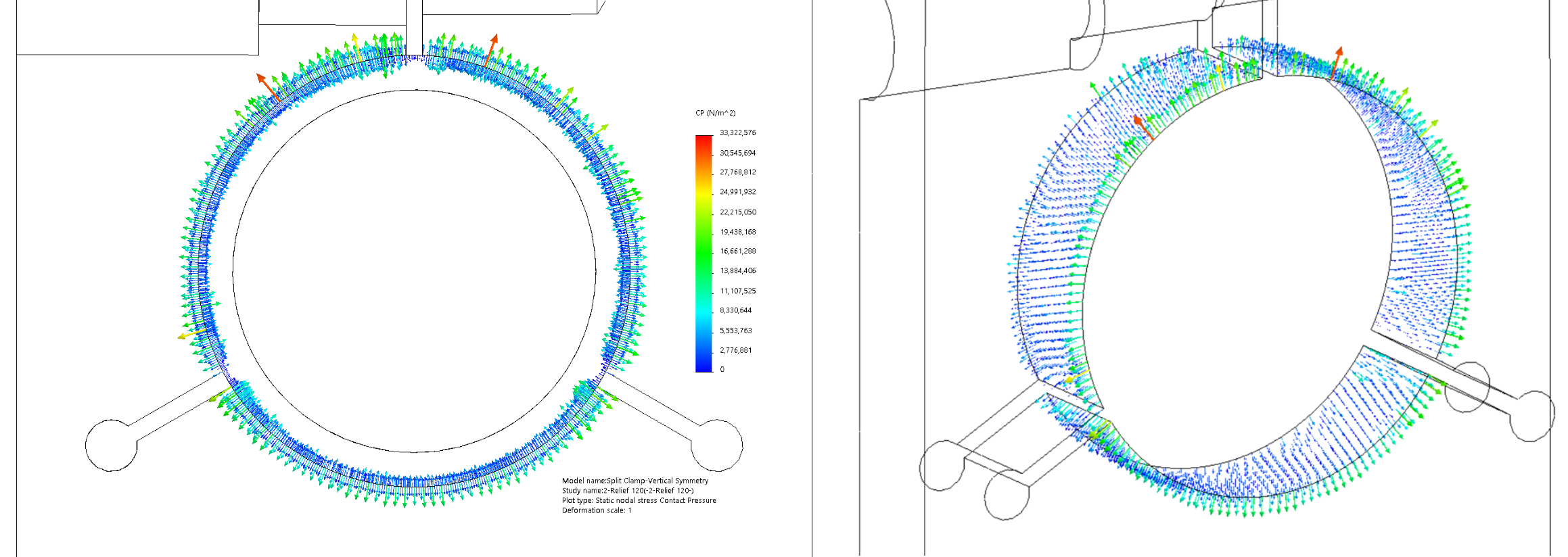
Figure: Contact pressure in a collet-style split clamp holding a lens cell with zero clearance
The magnitude of the pressure is hard to read in the vector plots above. The figures below graph the contact pressure along the back edge of the clamps. This isn’t a real edge corresponding to an edge in the physical part; it’s created by sectioning the model about the symmetry plane. As such, it represents contact pressure internal to the part, away from the edge effects of the real sharp edges on the clamp.
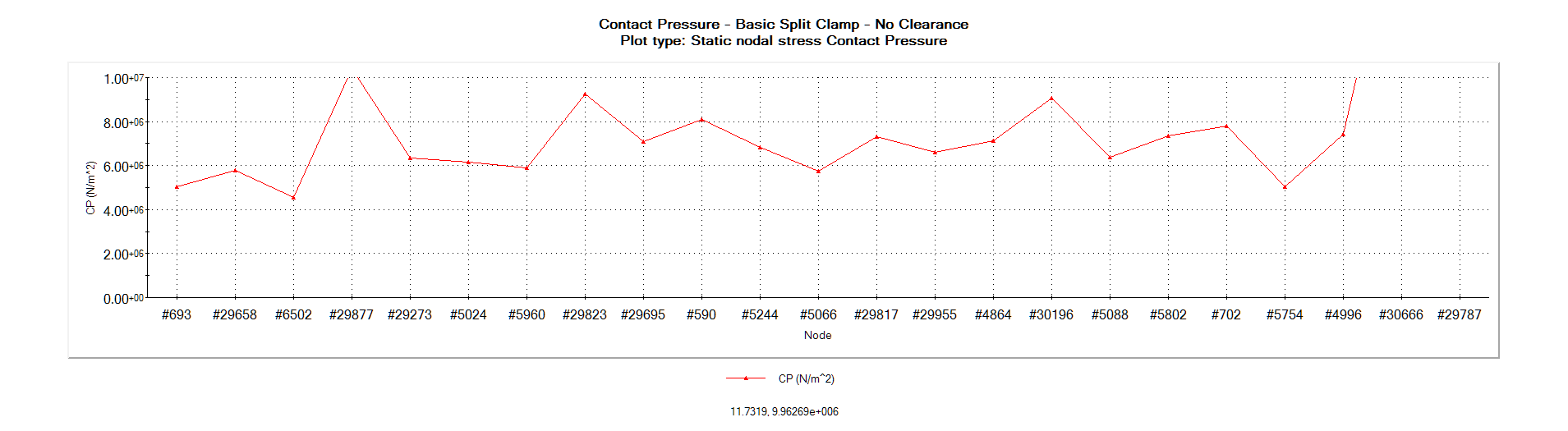
Figure: Contact pressure plot in a basic split clamp holding a lens cell with zero clearance
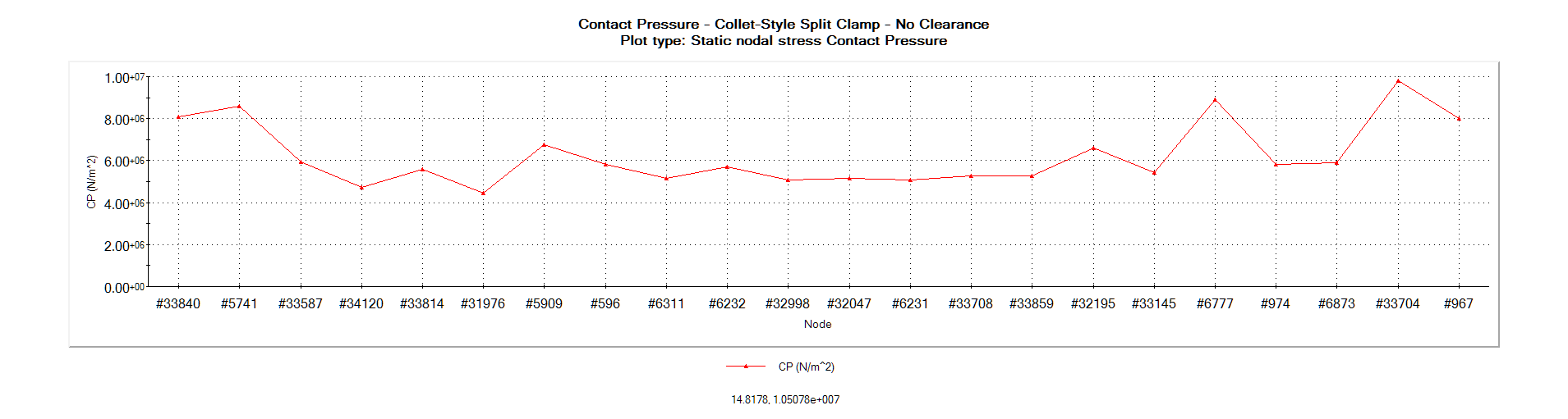
Figure: Contact pressure plot in a collet-style split clamp holding a lens cell with zero clearance
Again, the performance of the basic and collet-style clamp is similar.
Differences begin to emerge when we view the deformed plot of the lens cell:

Figure: Contact pressure on lens cell with zero clearance – Basic (left) and collet-style (right) split clamps – Scale: 100X
As we noted earlier, an ideal clamp would perform like a shrink fit: Both the clamp and the lens cell would remain perfectly round and there would be uniform pressure all around.
In the zero clearance case, the collet-style clamp approaches this ideal, with the lens cell appearing round even at 100X scale. The stiffness of the collet-style clamp would be independent of load direction.
In the basic clamp, the deformed lens cell is clearly egg shaped. You would expect some variation in stiffness response to lateral loads. But contrary to Kittell’s suggestion, I would expect the basic clamp to be stiffer against vertical loads than horizontal loads; imagine holding a cylinder with your thumb and forefinger on the top and bottom so as to squeeze it into the shape shown, then press on it.
Case 2: 0.2% Clearance Between Lens Cell and Clamp
In the clearance case, the lens cell in the basic clamp develops even more asymmetry, with two distinct high-pressure points and corresponding impressions at about 120 degrees to either side of the peak. Slightly “up” from the high-pressure patches, the pressure seems drop significantly below the norm. The shape is still clearly oval.
The lens cell in the collet-style clamp also begins to deviate from circular, but it has a rough rotational symmetry every 120 degrees.
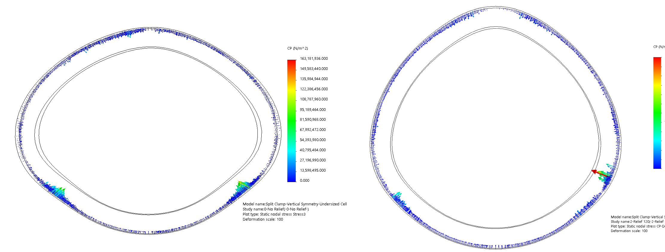
Figure: Contact pressure on lens cell with 0.2% clearance – Basic (left) and collet-style (right) split clamps – Scale: 100X
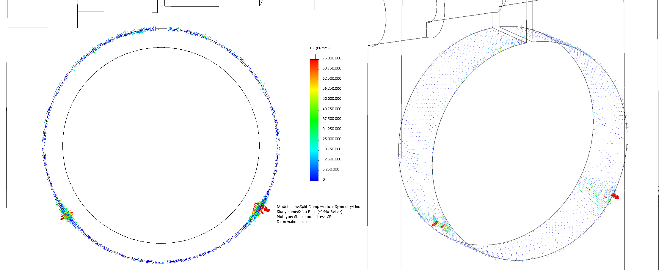
Figure: Contact pressure in a split clamp holding a lens cell with 0.2% clearance
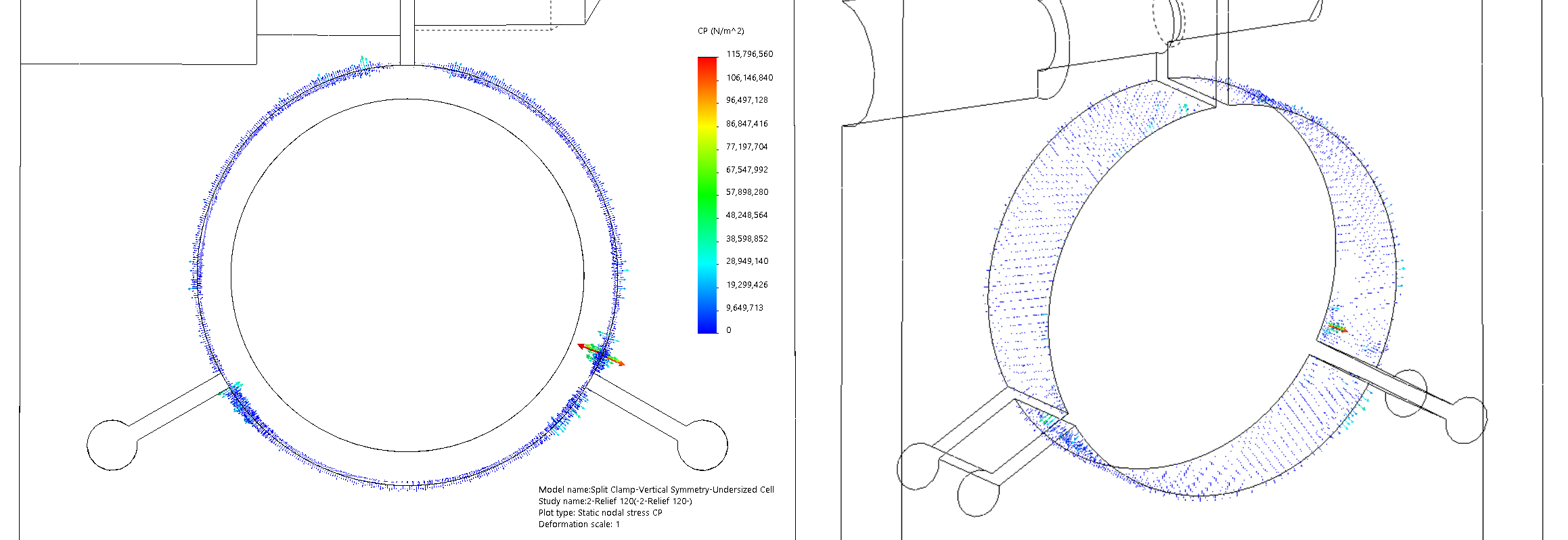
Figure: Contact pressure in a collet-style split clamp holding a lens cell with 0.2% clearance