
Kinematic components are the set of balls, vees, and other shapes that come into point contact with each other to locate the structural members of a kinematic mount relative to one another. In this article, we discuss the desirable material properties of kinematic components and the criteria used to evaluate materials for your kinematic mount design. We also provide a quick reference sheet for comparing the relevant properties of common kinematic component materials to help you select the right material for your design.
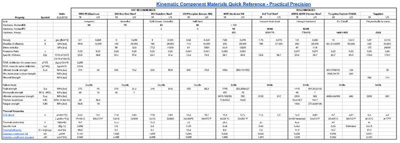
Download a high-resolution PDF of the quick reference and refer to it throughout the discussion:
Don’t let the wrong material compromise your design
The point contact between kinematic components results in high Hertzian contact stress under even moderate loads, which can compromise the performance or limit the life of a kinematic mount or coupling. The minute deflection of the surfaces under that load is a measure of the stiffness of the joint, which affects accuracy, especially under variable loads. These local deformations also resist the tendency of the components to settle into their ideal position, so smaller is better. And the integrity and accuracy of that interface can be compromised due to corrosion; wear; or micro-yielding under the influence of environmental effects and operating loads including humidity, temperature change, shock, vibration, and disassembly/reassembly.
Given these concerns, ideal materials for kinematic contacts are hard, stiff, high strength, and corrosion resistant. Mating contact materials must also be compatible to avoid problems with galvanic corrosion, galling, or excessive friction.
Some materials that may satisfy these criteria include:
- Hardened metals such as tool steel and 440C stainless steel
- Ceramic metal composites (cermets) of such material as tungsten carbide
- Hard minerals such as sapphire
Whether a given material is suitable for a specific application depends not only on the properties of the material but also on the geometry; operating and environmental loads; and performance requirements of the system.
These criteria and their applicability to certain designs are discussed below. Table X summarizes them.
About the Material Selection Quick Reference Sheet
The Materials
The table lists properties for a selection of kinematic component materials ranging from the common place to the exotic, including:
- 17-4PH H900 stainless steel
- 440C stainless steel
- A-2 tool steel
- Chrome steel
- Tungsten carbide, and
- Sapphire
Commercial, off-the-shelf kinematic components are available in each of these materials. And custom parts can be fabricated from them as well (even tungsten carbide and sapphire) as described below in Machinability and Fabrication. This is not an exhaustive list; other materials may be suitable for your application, as well. You can use the table as a reference for evaluating alternative materials. If you know a material that you think should be included in the table, please let us know via the contact form.
Wait… what is aluminum doing here?!
The table also includes entries for 6061-T6 aluminum, phosphor bronze, 303 stainless steel, and 304 stainless steel, which are not recommended for use as kinematic components. So why are they included?
- For comparison – Ideal kinematic component materials are described as hard and strong. Contrasting them with poor choices helps to define those attributes.
- For convenience – These softer materials are often used in conjunction with kinematic components to create structural members, threaded bushings, and other parts of a kinematic mount. It can be helpful to see properties for all of them in one place.
- For edge cases – Despite their drawbacks, sometimes the available space claim or some other constraint dictates that they be used as kinematic components, often combining features such as a v-groove in the structural component.
Softer materials such as 303 stainless are also useful for quickly prototyping a design and testing its basic functionality. In a controlled environment, with a fixed load and adjustment during alignment, these parts can often be assembled and disassembled with very high repeatability. The parts can then be implemented in a harder but more difficult to fabricate (and longer lead time) material for the final design.
Regardless of materia, designs should always be verified as discussed below in Design Verification Through Analysis and Testing.
The Properties
A Note on Hertzian Contact
It is impossible to discuss the suitability of a material for use as a kinematic components without mentioning Hertzian contact and Hertzian contact stress, since they directly relate to the performance and life of the mount. But these are complex topics deserving of their in-depth own article. For the sake of this article on material selection, contact area, deflection, and stress and their relationship to material properties will be discussed only qualitatively, not quantitatively or analytically. A future article will expand on them.
A Caution About the Temperature Sensitivity of Materials
Material properties and thermal properties in particular tend to vary with temperature, so the operating temperature range as well as the temperature at which the system is built and aligned must be considered when selecting materials.
Contact the vendor of the material for properties at temperature. Research papers can sometimes fill in gaps in that information. For critical applications and when other sources are not available, physical testing is recommended, as described below in Design Verification Through Analysis and Testing.
Hardness
The materials are listed in terms of increasing hardness. Hardness is a measure of the resistance of a material to local deformation under a defined load applied by a small shape called an indenter; harder is better. This is highly relevant for kinematic components, since deformation under point contact is proportional to contact stress and also resists free motion between the kinematic components.
Hardness is often related to the yield strength of the material. And for some materials, it can be purposefully modified by manufacturing processes. This ability to be hardened is the reason that 440C stainless steel is a good choice for a kinematic component but 303 stainless steel is not.
Hardness is determined experimentally using different loads and indenter shapes. Hardness varies so widely among materials that a single test method and scale cannot cover them all. The table presents presents hardness using overlapping Rockwell B, Rockwell C, and Knoop scales to give some sense of the range from softest to hardest. For a given material, bold face indicates a value that was experimentally determined. Other values are approximate conversions for comparison purposes only.
Modulus of Elasticity, Deflection, and Stiffness
Unlike hardness, which can sometimes be manipulated and is related to strength, modulus of elasticity is an intrinsic property of the material related to stiffness. In general, it does not vary with manufacturing process. It’s the ratio of the longitudinal stress to the corresponding strain in the elastic regime; it has the same units as stress. The higher the modulus of elasticity, the stiffer the material.
The point contact between kinematic components is only a point when considered at a large scale. In practice, it produces an elliptical contact area with the amount of deflection varying from a maximum at the center of the ellipse to zero at the perimeter, as shown in the image from Wikipedia below. The amount of deflection varies in each component and depends on the modulus of elasticity (E) and Poisson’s ratio (ν) of each material, as well as the shape of the parts and the applied load.
For a given load, the amount of deflection along the line connecting the centers of curvature of the parts is a measure of the normal stiffness of the joint.
The higher the modulus of elasticity of the materials, the less the deflection, the smaller the contact area, and the stiffer the joint. This is significant for kinematic mounts because:
- Contact area and deflection relate to the Hertzian contact stress, which can cause failure, as is discussed in the next section.
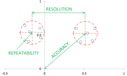
- The deformation creates a resistance to motion that can be thought of like a flat tire. It resists the tendency of the contacts to assume their “ideal” relative position on initial assembly or to return to that position after being moved or separated, such as under the effects of thermal expansion or vibration. This reduces the repeatability of the mount, which limits the accuracy.
- If the load carried by a kinematic mount is variable, the position and orientation of the mount will vary as a function of the stiffness. So a stiffer joint results in greater consistency for a range of loads. This affects the accuracy of the mount.
- The stiffness of the joint contributes to the overall stiffness of the system and therefore its natural frequency.
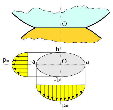
Source: https://commons.wikimedia.org/wiki/File:Hertz.svg
Failure Mode and Strength
The point contact between kinematic components results in high Hertzian contact stress under even moderate loads. Ductile materials and brittle materials will fail by different modes at different locations within the contact ellipse shown above:
- Ductile materials will fail by yielding where the shear stress is maximum at a point below the surface. For ductile materials, the shear strength can be approximated as 57.7% of the yield strength.
- Brittle materials will fail by fracture where the tensile stress is maximum, at the edge of the ellipse. The ultimate compressive strength is the relevant material property in this case.
As indicated in the table, recommended materials for kinematic components are considered brittle.
You will want to apply an appropriate factor of safety that takes into consideration the usual uncertainties in calculations, material properties, and operating conditions as well as the consequences of failure.
Zero Wear Criterion
For ductile materials (not recommended), a factor of safety of 5 or greater may be justified if significant movement between the kinematic contacts can be expected (such as in parts that are intended to be interchangeable or when subject to vibration or temperature changes). This is based on the zero wear theory, which states that wear will not exceed the surface finish of a polished metal part when:
τmax / τys ≤ 0.2
Yielding and Micro-Yielding
Kinematic components that also play a structural role – such as a single piece of 440C stainless steel with three v-grooves forming one half of a Maxwell-style kinematic mount – may also warrant higher than normal factors of safety. For many metals, the yield strength is defined as the point at which 0.2% plastic strain occurs. That is a deformation of .05 mm over a distance of only 25 mm, which is unacceptable for precision applications.
Alternatively, the micro-yield strength (MYS) of the material can be used, if known. Micro-yield strength is defined as the stress that causes a permanent strain of 1 part in 1 million. Fortunately, the relationship between yield and micro-yield strength is not linear, otherwise 6061-T6 aluminum, with a yield strength of 276 MPA, would have a micro-yield strength of only 138 kPa. In actuality, the micro-yield strength of 6061-T6 aluminum is 69 MPa.
Values for micro-yield strength are not readily available for many materials. However, for closely related materials, MYS tends to be proportional to yield strength.
Structural Efficiency Figures of Merit
This category of properties primarily relates to materials that are used for structural components. They are included here primarily for completeness, although kinematic components may sometimes play a dual role as a structural member as described above. These properties will be discussed in depth in an article on selecting materials for structural members in precision applications. But of particular interest – especially when distinguishing between strong and stiff materials – is the specific stiffness.
When a mount is subject to a significant or significantly varying external load, high modulus of elasticity (E) materials such as steel will minimize the deflection or the change in deflection under load.
But when the weight or inertia of the mount itself is a significant part of the load (i.e., self-weight deflection), specific stiffness is a better indicator of the relative performance of materials. Specific stiffness is the ratio of modulus of elasticity to density:
Specific stiffness = Modulus of elasticity / density = E/ρ [Units: 106 m2/s2]
It is surprisingly consistent for many materials. For example, steel, aluminum, magnesium, and glass all have a specific stiffness in the range of 25-28 x 106 m2/s2 while brass and cast-iron have a value in the range of 13-14. But some exotic materials have exceptional values: tungsten carbide has a value of 42.7, sapphire of 109.6, silicon carbide of 140, and beryllium of 155.
Thermal Distortion Figures of Merit
Similarly, thermal distortion figures of merit – thermal diffusivity, steady state distortion coefficient, and transient distortion coefficient – are included for completeness and convenience, but they will be discussed in depth in another article.
Corrosion Resistance
Corrosion resistance cannot be quantified in a single word or phrase. Whether parts will fair well over time depends on the material, finish applied, mating materials, the operating environment, and sometimes even residual effects of producing the parts. The ratings given in the table are only the most general guidelines based on performance of a material under common conditions in comparison to similar materials. Corrosion resistance can also be temperature dependent.
Chromium tends to improve corrosion resistance; it’s what gives stainless steel its resistance.
Carbon is the binder in most tungsten carbides, which can degrade corrosion resistance. For increased corrosion resistance, there are formulations that substitute nickel for carbon.
The addition of sulfur, such as in 303 stainless steel to enhance its machinability, can also reduce corrosion resistance. In certain high vacuum applications such as sputtering, the sulfur can also contaminate the chamber and product so that less machinable materials such as 304 stainless steel may be used.
You must consult with material vendors and research your own application to determine if a given material is suitable.
Machinability and Fabrication of Kinematic Components
The same properties that make a material suitable for use as a kinematic contact can often make it unsuitable for use as a structural component:. It can be:
- Difficult and expensive to machine
- Brittle and unable to withstand bending loads
- Heavy
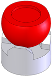
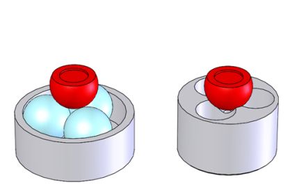
A common solution is to use custom or off-the-shelf kinematic contacts of the appropriate material mounted securely to the structural members. They may be:
- Secured with hardware
- Press-fit or bonded
- Simply captured by the preload within mating features.
Precision balls are readily available in a wide range of materials and sizes, including exotic and difficult to machine ones. Commercial, off-the-shelf flats, vees, cylinders, and sockets are also available but in a smaller variety of sizes and materials. So when a material combination involving one of these is needed, especially when space is constrained, it may be more practical to purchase a ball made of the exotic material and make the mating components out of easier to machine metals.
Machining Hard Metals
When a complex shape such as a single part with three radial v-grooves is needed but the space claim or other constraint prevents the use of inserts, the part may need to be machined from whole (e.g., rod or billet) or from a near net shape (e.g., a casting or weldment).
Before hardening, materials such as 440C stainless steel, A-2 tool steel, and chrome steel can be readily machined to create kinematic components such as vees, cones, and trihedral sockets or more complex parts that incorporate these features. But it is sometimes necessary to machine these materials after hardening, such as to:
- Achieve accuracy levels that are difficult to maintain after heat treating
- Rework a custom part
- Modify an off-the-shelf component
Traditional machining becomes significantly more difficult, time consuming, and expensive – if not impossible – in the hardened state. Surfaces can be ground, honed, or lapped.
Although not as hard as 440C stainless steel or chrome steel, 17-4PH H900 stainless steel and A-2 tool steel have advantages in terms of machinability, which is especially helpful for complex geometries and parts. Reggie Tobias, owner of Hitek Hardware, notes:
- 440C is challenging to machine and typically requires post heat treatment grinding to ensure precision.
- 17-4PH can be machined to less than a 0.2 μm (8 microinch) finish and has little deformation during heat treatment, thus it doesn’t require post heat treatment grinding.
- A-2 tool steel is a reasonably stable, low cost, heat treatable material. It machines like butter in the annealed state. Surface finishes of 0.1-0.2 μm (4-8 microinch) are possible. It is quite corrosion resistant in the usual environment that these kinds of mechanisms are used. And post hardening polishing is a breeze.
Techniques such as electrical discharge machining (EDM) can be used to modify electrically conductive materials such as 440C, tool steel, and tungsten carbide. EDM even enables features that are difficult or impossible to create using other material removal processes such as milling or turning.
EDM only removes material, but features can added as well by first machining a hole or other feature into which another part is pressed, bonded, or fastened.
Fabricating Sapphire Parts
Sapphire can be machined, as demonstrated by its use in jewel bearings, which are available as conical detents and in other forms that lend themselves to kinematic mounts. When used as an optical component, sapphire may be machined to produce complex edge profiles; add bevels or rounds; and even form curved surfaces. Given the expertise and access to material needed to produce sapphire parts, if you need a custom sapphire component, you will likely need to work with a vendor that specializes in it.
The possibilities for complex sapphire parts may surprise you, such as the externally threaded sapphire parts from Rayotek shown on this page: https://rayotek.com/glass_custom_dome_tube_rod_prism.htm.
Fabricating Tungsten Carbide Parts
Even more so than with sapphire, if you need a custom tungsten carbide part, you will need to work with a specialty vendor. Tugsten carbide can be produced in near net shape and readily machined before sintering, which produces its final, hardened state. In the hardened state, it can be ground or machined via EDM, thanks to its electrical conductivity.
Various techniques can also be used to join tungsten carbide to other materials.
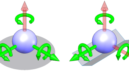
Magnetism
If a kinematic component (or a structural member) is attracted to magnets, they can be used to apply a preload inline or nearly inline with the contact points, minimizing distortion. In addition, magnetic preload is consistent over multiple assembly and disassebmly operations, without the hysteresis or variability of various mechanical locking techniques.
In applications in which temperature control is critical, this technique can also be used to thermally isolate parts by minimizing the number of thermal conduction paths.
Kinematic component materials can be classified as:
- Ferromagnetic – Not only are these materials strongly attracted to magnets, they can become magnetized themselves.
- Strongly attracted, attracted, or slightly attracted to magnets. Sometimes described as strongly magnetic, magnetic, or slightly magnetic.
- Non-magnetic – Not attracted to magnets. Austenetic stainless steels (e.g., 303 and 304 stainless) are non-magnetic but can become slightly magnetic through cold-working. Annealing can return them to their non-magnetic states.
Design Verification Through Analysis and Testing
The tradeoff for a kinematic mount’s high repeatability, stability, and ease of adjustment is high Hertzian contact stress and – as a result – relatively low load rating. High precision applications can also be sensitive to the deflection of the joint (especially under dynamic loads) and the stiffness of the joint. Friction, galling, and other factors also affect the repeatability and life. All of these are highly sensitive to the choice of mating materials and the interactions between them.
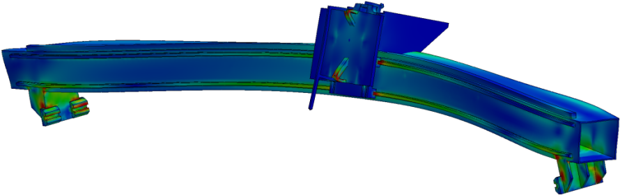
It is important that you verify your material choices (and all aspects of your design) through proper analysis. Minimally, calculate the Hertzian contact stress to verify that it is within acceptable limits for your application. The same set of calculations can determine the stiffness of the joint and its deflection under load.
There are useful guidelines and research available on the repeatability of kinematic mounts, but for critical applications, the most effective solution is to perform physical testing and take measurements. Also, material properties may not be available for your choice of materials, combination of materials, or operating conditions. Even when available, they typically report a wide range of values over a wide operating range and are extrapolated from very specific test cases.
An effective and efficient development process incorporates physical testing in a number of forms:
- Material testing to determine fundamental properties of materials under operating conditions and in combination.
- Prototyping and test of an element of a design or a simplified version of a design. This provides early feedback on not only the performance of the materials but also on the basic design form.
- Testing of the complete or nearly complete design, with special attention paid to repeatability over multiple assembly and disassembly operations and to stability over time when subject to operating conditions. Repeatability can actually improve over time due to run in, but it could also begin to degrade.
- Accelerated life testing, environmental testing (e.g., exposure to the elements), and even testing to failure to determine the limits of the design.
A kinematic mount is typically only part of a larger system, so determining the true impact of these parameters on the repeatability, accuracy, and performance requires analysis and testing of higher levels. But the stress, deflection, and stiffness and an understanding of the material interactions are key inputs.
A Special Thanks to Reggie Tobias of Hitek Hardware
Reggie Tobias, owner of Hitek Hardware, has sixty years of experience designing and manufacturing mechanical components and assemblies for precision machines and instruments. He made valuable contributions to this article, especially regarding (1) machinability considerations of 440C stainless, 17-4 PH stainless, and tool steel when fabricating custom kinematic features, especially when they integral to a larger component, (2) environmental considerations for some materials, and (3) “edge” cases and circumstances for which softer materials may be used. Hitek Hardware provides off-the-shelf and custom components and assemblies for kinematic mounting and adjustment in a variety of materials.`
I updated the Kinematic Component Materials Quick Reference to include the material 17-4 PH H900 Stainless Steel and the properties Magnetism, Corrosion Resistance, and Machinability.
Good afternoon Mr. Campbell, could you suggest any company that produces such balls? I am looking for these part for an application in may lab. Thank you
Hello Paolo,
Specifically for precision balls in different materials, Bal-Tec (precisionballs.com) is a great source, although there website is a little difficult to navigate. For example, here is a selection of tungsten carbide balls:
https://precisionballs.com/catalog/index.php?cPath=29
They can modify balls as well.
As for other hardened kinematic components, Newport offers a set of tungsten carbide cones, vees, and flats:
https://www.newport.com/f/carbide-pads?q=kinematic%20components:relevance:isObsolete:false
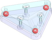
Hitek Hardware (https://www.hitekhardware.com/index.php?p=home) offers a range of hardened components, including ones with through holes that allow for preload to be applied directly inline with the mount. Hitek even offers assemblies that incorporate a vee, an adjustment screw, a locking collet, and a preload. The Hitek product line includes a range of stainless and tool steels.
Thank you Rob, I will start my search there!
Hi Rob, congratulations on this excellent web page.
I’m designing a pair of kinematic couplings for two structures in a very specific SLA 3D printer, and I’m amazed I can only find two vendors of kinematic components in the USA (and none in Europe). At Bal-Tec they seem to know everything about spheres and kinematic couplings, but they do not have some mid-sized components (for example trihedral or conical cups). Hitek hardware also has a strange mixing of components in different materials and price variation that I do not understand. Newport, besides their kinematic platforms that do not suit me, has these tungsten carbide components, but they are way small for my application and I do not find corresponding spheres…
Do you know of any other manufacturer?
Thank you!
Jose, The reason Hitek has a strange mix of components and materials is that all of our proucts were originally designed to customer specifications. The price variations depends on the popularity of the product in the market, hence, the voume that we manufacture or purchase the part determines the price.
Reggie Tobias
Hitek