In this video, we look at how to layout a kinematic mount and optimize the design for stability and repeatability using the Maxwell criterion.
To download a kinematic mount CAD model to explore the concepts we discuss to and freely adapt it for your own use, click the link below:
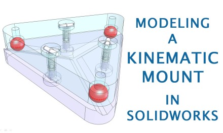
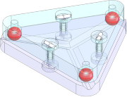
This is a Maxwell style kinematic mount, which uses three balls in three v-grooves to establish six points of contact, exactly constraining the top plate relative to the bottom.
The equilateral triangle layout is very common, and its symmetry has several a number of advantages, including stability and maximization of usable space between the supports.
An isosceles triangle layout may fit better in certain applications or may be preferred if there is greater sensitivity to alignment in one axis than another.
But many applications have design constraints that make it difficult to use straightforward layouts.
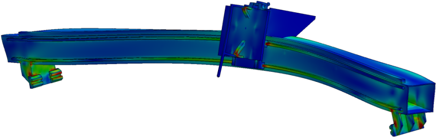
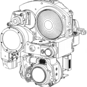
This is an extreme example, from a stabilized gimbal and payload that I helped to develop; these are patent drawings.
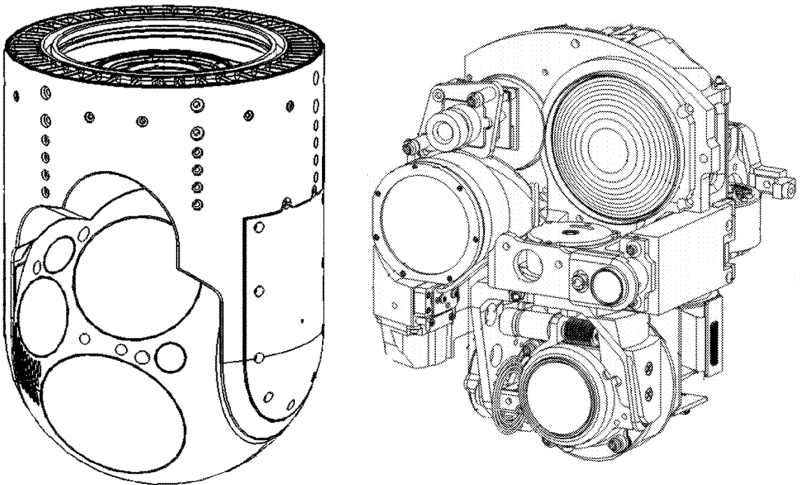
The optical axes of the various sensors need to be aligned to each other, a process called boresighting. Kinematic mounting is used for a number of these mounts and adjustments. There are two challenges in designing those kinematic mounts:
- The space claim for each sensor is not only tight but oddly shaped as well; some sensors even wrap around each other. So the first order concern is simply getting all the sensors to fit. Laying out the kinematic mounts is secondary.
- Final boresighting is done to the complete assembly, with the covers installed. So adjustment and locking mechanisms need to be positioned and oriented so that they are accessible from the outside, through small access ports.
Given these constraints, simple, aesthetically appealing equilateral or isosceles triangle layouts simply won’t work. We need to make it fit as best we can, while still maintaining high stability and repeatability.
Consider two scenarios:
- Intentional assembly, including initial assembly, replacement as a part of service, or swapping of interchangeably components that use the kinematic interface.
- Micro-disassembly and reassembly, which can occur when the mount is subject to shock, vibration, or differential thermal expansion. Anything, really, that causes a momentary separation or movement of any of the contact points.
Although the kinematic mount theoretically has one unique, fully constrained position that it should assume, various effects – such as friction, elastic deformation, or contamination – can prevent it from achieving or returning to that position after each assembly.
Virtually any arrangement of 3 balls in 3 v-grooves will establish 6 points of contact that fully constrain the kinematic mount. But not all arrangements are equally stable and repeatable.
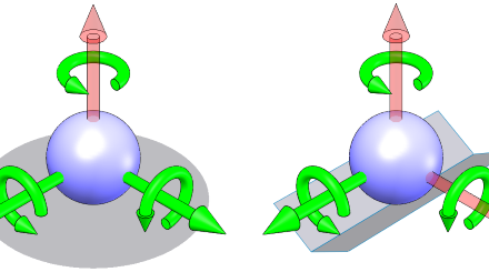
Let’s start developing our understanding of this by looking at an extreme example.
If a torque is applied or some slight movement is imparted, this arrangement offers virtually no resistance or tendency to return to its original state, because the reaction forces are perpendicular to the motion.
The Maxwell criterion for laying out a kinematic mount
James Clerk Maxwell, the scientist most associated with the 3 balls in 3 v-grooves kinematic mount, proposed a criterion for ensuring stability. I’ll include the full criterion and references in the article that accompanies this video.
But to paraphrase and simplify:
To promote stability, arrange the bearing surfaces such that, if one surface is removed, the direction in which the part would then be free to move is as close to perpendicular to that surface as possible.
Satisfying the Maxwell criterion for a planar mount
Satisfying the Maxwell criterion is greatly simplified in the case of a planar arrangement of three balls in three v’s. Simple geometry can be used to optimize even an arbitrary layout of 3 supports, like the one we have here.
If we define a triangle with a corner at the center of each ball, then the centerline of each v-groove should bisect the corresponding angle. These three lines intersect at the centroid of the coupling. Note that this is not the same as the geometric centroid of the triangle in any case except for an equilateral triangle, so don’t take that shortcut.
To fully understand the kinematics of the mount and the benefit of the Maxwell criterion, we also need to define instantaneous centers of rotation (IC’s) for each pair of supports.
Each ball-in-v support has two force vectors that intersect at the center of the ball, defining a plane.
So we have three planes with three intersections defining three axes, which are the instantaneous centers of rotation.
Any adjacent pair of ball-in-v supports has four points of contact, leaving only two degrees of freedom. Let’s look at the case of supports one and three.
The first degree of freedom is rotation about the axis through the center of the two balls. The points at support two will resist this motion. Of course, a preload mechanism of some kind is required to positively load the ball against the v-groove under all circumstances.
The second degree of freedom is rotation about the instantaneous center, which is coming out of the screen towards us in the video:
- The reaction forces at those two supports offer virtually no resistance to rotation about the instantaneous center: The force vectors are normal to the circle.
- Conversely, we see that the reaction forces at the third support are tangent to the arc, so they offer their full resistance.
So support two resists rotation about IC 3-1, support three resists rotation about IC 1-2, and support one resists raisin about IC 2-3.
The combination of the grooves in this arrangement, satisfying the Maxwell criterion, offers resistance to motion about all three instantaneous centers.
So in designing a kinematic mount, complying with the Maxwell criterion promote stability and repeatability. In the case of a planar mount, this means ensuring that the v-groove centerlines bisect the corresponding apex angles.
Learn more in the Kinematic Mount Design series
This articles is part of the Kinematic Mount Design series, where we explore the aspects of kinematic mount design in detail, including first principles like kinematic mounting and practical considerations like machining trihedral sockets.
Visit the Kinematic Mount Design page to learn more and to me notified of future articles.